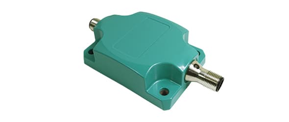
| Application | 1-Axis Position Monitoring and Leveling |
| Measurement Range | 360° |
| Accuracy (INL) | ±0.10° |
| Resolution | 0.01° |
| Repeatability | ≤0.05° |
| Cycle Time Base Sensor | 1 ms |
| Supply Voltage | 9 – 30 VDC |
| Current Consumption | ≤ 65 mA @ 10 V DC, ≤ 60 mA @ 24 V DC |
| EMC: Emitted Interference | DIN EN 61000-6-4 |
| EMC: Noise Immunity | DIN EN 61000-6-2 |
| Reverse Polarity Protection | Yes |
| Short Circuit Protection | Yes |
| MTTF | 440 years @ 40 °C |
| Min Temperature | -40 °C (-40 °F) |
| Max Temperature | +85 °C (+185 °F) |
| Storage Temperature | -40 °C (-40 °F) – +85 °C (+185 °F) |
| Temperature Gradient | 0.004°/ K |
| Temperature Gradient | 0.004°/ K |
| Protection Class (Housing) | IP68/IP69K |
| Shock Resistance | ≤ 100 g (half sine 6 ms, EN 60068-2-27) |
| Vibration Resistance | 1.5 mm (10 Hz – 58 Hz) & ≤ 20 g (58 Hz to 2000 Hz) |
| Housing Material | Zinc |
| Potting Material | None |
| Weight | 290 g (0.64 lb) |
| Interface | J1939 |
| Settling Time | min 30 ms; default 200 ms (dependent on filter settings) |
| Output Driver | Transceiver (ISO 11898) |
| Transmission Rate | 125 kBaud, 250 kBaud, 500 kBaud |
| Default Transmission Rate | 250 kBaud |
| Default Node ID | C0h |
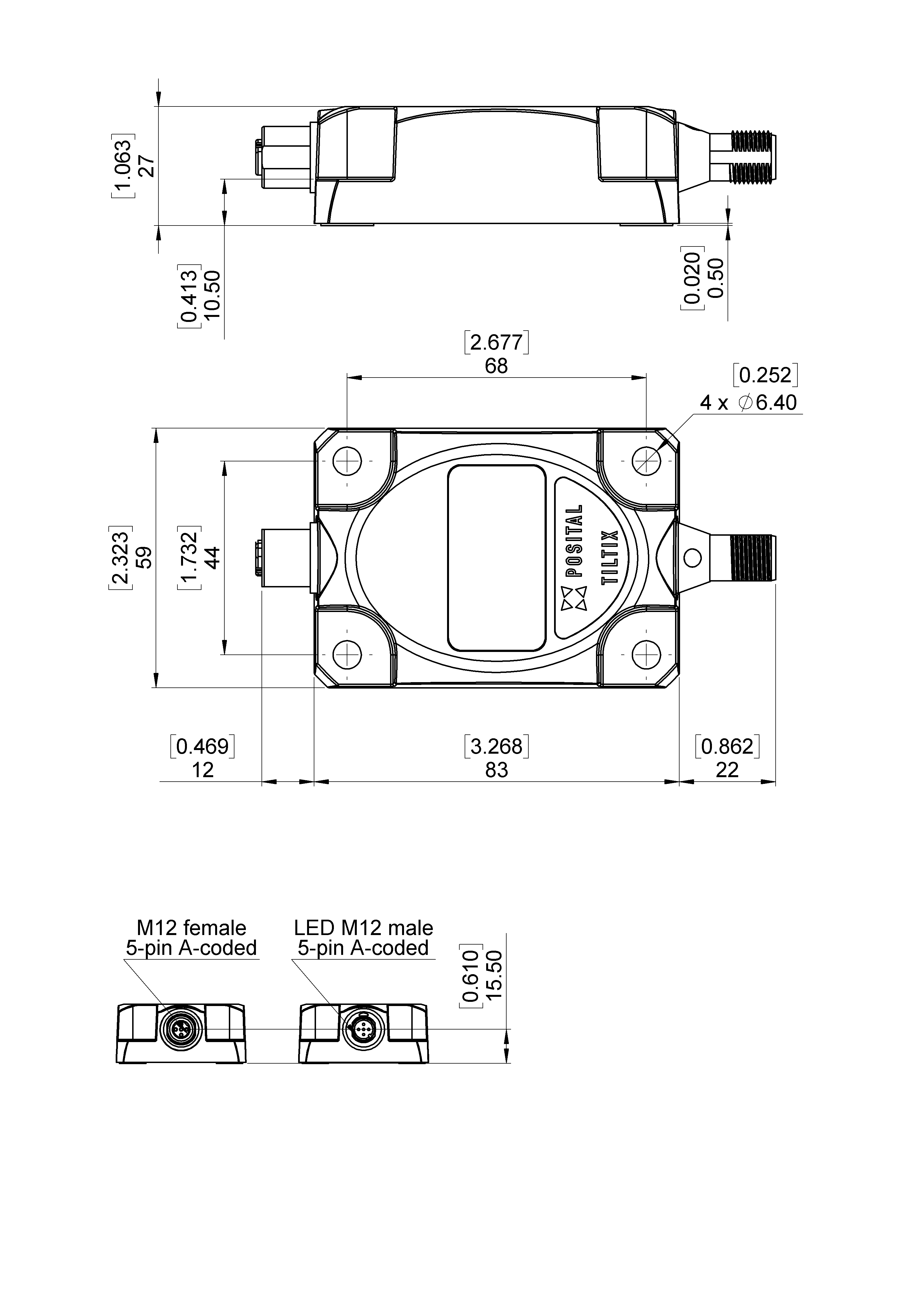
| Connection Type | Connector 2 x M12 (CAN) Male+Female |
| Connector 1 | M12, Male, 5 pin, a coded |
| Connector 2 | M12, Female, 5 pin, a coded |
| Product Life Cycle | Prototype |

| Signal | Connector | Pin Number |
|---|---|---|
| Power Supply | 1 | 2 |
| GND | 1 | 3 |
| CAN High | 1 | 4 |
| CAN Low | 1 | 5 |
| Not Connected | 1 | 1 |
| Power Supply | 2 | 2 |
| GND | 2 | 3 |
| CAN High | ||

| 2 |
| 4 |
| CAN Low | 2 | 5 |
| Not Connected | 2 | 1 |