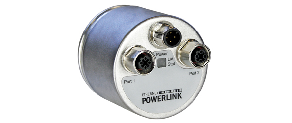
| Interface | Ethernet POWERLINK V2 |
| Profile | Powerlink V2, DS-406 |
| Features | Round Axis + Integrated Hub |
| Transmission Rate | 10 / 100 Mbit |
| Interface Cycle Time | ≥ 400 µs |
| Programming Functions | Resolution, time base and filter for velocity, preset, counting direction, IP-Address |
| Output Driver | Ethernet |
| Supply Voltage | 10 – 30 VDC |
| Current Consumption | ≤ 230 mA @ 10 V DC, ≤ 100 mA @ 24 V DC |
| Power Consumption | ≤ 2.5 W |
| Start-Up Time | < 1 s |
| Reverse Polarity Protection | Yes |
| Short Circuit Protection | Yes |
| EMC: Emitted Interference | DIN EN 61000-6-4 |
| EMC: Noise Immunity | DIN EN 61000-6-2 |
| Electrical Lifetime | >10⁵ h |
| Technology | Magnetic |
| Resolution Singleturn | 13 bit |
| Resolution Multiturn | 12 bit |
| Multiturn Technology | Self powered magnetic pulse counter (no battery, no gear) |
| Accuracy (INL) | ±0.0878° (≤ 12 bit) |
| Code | Binary |
| Protection Class (Shaft) | IP65 |
| Protection Class (Housing) | IP66/IP67 |
| Storage Temperature | -40 °C (-40 °F) – +85 °C (+185 °F) |
| Humidity | 98% RH, no condensation |
| Max Temperature | +85 °C (+185 °F) |
| Min Temperature | -40 °C (-40 °F) |
| Housing Material | Steel |
| Housing Coating | Wet coating (RAL 9006 White Aluminium) + Cathodic corrosion protection (>720 h salt spay resistance) |
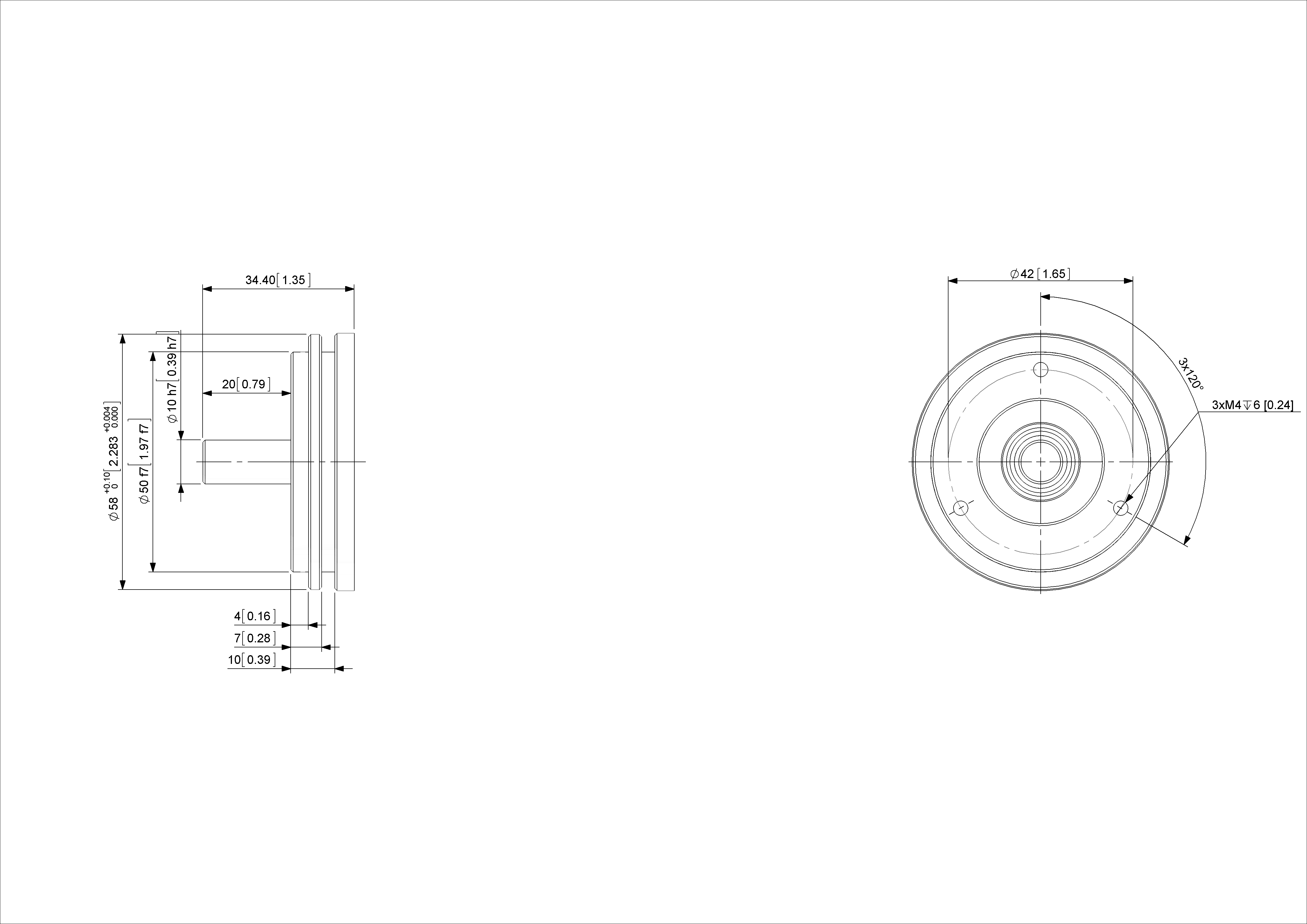
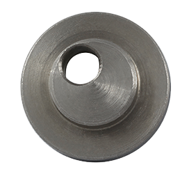
| Flange Type | Synchro, ø 58 mm (Y) |
| Flange Material | Aluminum |
| Shaft Type | Solid, Length = 20 mm |
| Shaft Diameter | ø 10 mm (0.39") |
| Shaft Material | Stainless Steel V2A (1.4305, 303) |
| Max. Shaft Load | Axial 40 N, Radial 110 N |
| Minimum Mechanical Lifetime(10^8 revolutions with Fa/Fr) | 420 (20N/40N), 145 (40N/60N), 100 (40N/80N), 55 (40N/110N) |
| Rotor Inertia | ≤ 30 gcm² [≤ 0.17 oz-in²] |
| Friction Torque | ≤ 3 Ncm @ 20 °C (4.2 oz-in @ 68 °F) |
| Max. Permissible Mechanical Speed | ≤ 12000 1/min |
| Shock Resistance | ≤ 100 g (half sine 6 ms, EN 60068-2-27) |
| Permanent Shock Resistance | ≤ 10 g (half sine 16 ms, EN 60068-2-29) |
| Vibration Resistance | ≤ 10 g (10 Hz – 1000 Hz, EN 60068-2-6) |
| Length | 56,7 mm (2.23") |
| Weight | 425 g (0.94 lb) |
| Connection Orientation | Axial |
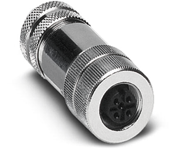
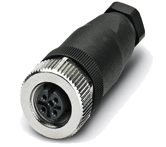
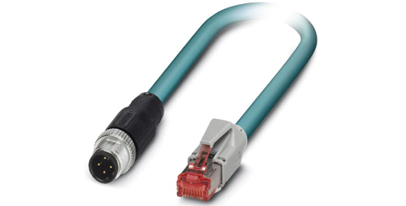
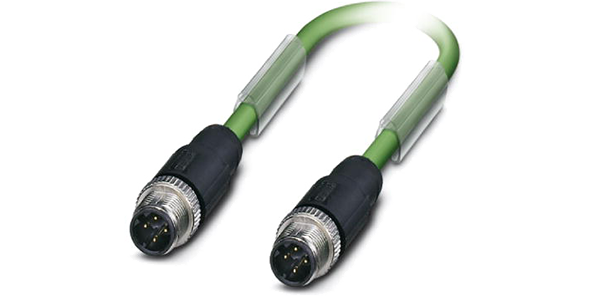
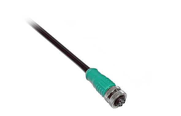
| Connector 1 | M12, Female, 4 pin, d coded |
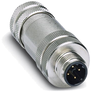
| Connector 2 | M12, Male, 4 pin, a coded |
| Connector 3 | M12, Female, 4 pin, d coded |
| Approval | CE |
| Product Life Cycle | Lab Sample |
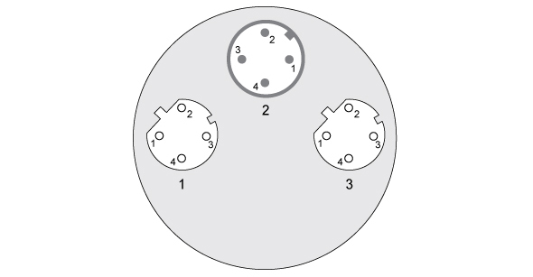
| Signal | Connector | Pin Number |
|---|---|---|
| Tx+ | 1 | 1 |
| Rx+ | 1 | 2 |
| Tx- | 1 | 3 |
| Rx- | 1 | 4 |
| Power Supply | 2 | 1 |
| Not Connected | 2 | 2 |
| GND | 2 | 3 |
| Not Connected | 2 | 4 |
| Tx+ | 3 | 1 |
| Rx+ | 3 | 2 |
| Tx- | 3 | 3 |
| Rx- | 3 | 4 |