


Encoder Troubleshooting & FAQ
Why is my Encoder Not Working?
Has your encoder failed during installation or operation? Has it stopped functioning and lacking any signal? If so, keep reading! Often, we do not have time to send a sensor back for complete analysis or even time to call an expert. That is why we have compiled some expert troubleshooting tips to get your encoder back up and running.
FAQ & Instructions
It is likely that the challenge(s) you are facing have already been encountered and solved. For all our interfaces, we keep dedicated, up to date FAQs and instructions, which can be found down here.
Interface | FAQ | Operating Instructions | Quickstart Instructions |
|---|---|---|---|
Accessory-UBIFAST Tool | |||
Accessory-SSI2USB | |||
Analog | |||
CANopen (Magnetic) | |||
CANopen (Optical) | |||
CANopen (Redundant) | |||
DeviceNet | |||
EtherCAT | |||
EtherNet/IP | |||
Inclinometer - Analog | |||
IO-Link | |||
IO-Link + Incr | |||
Modbus RTU | |||
Modbus TCP/IP | |||
Powerlink | |||
Profibus | |||
Profinet | |||
PROFIsafe | |||
SAE J1939 |
Finding the Root Cause
Encoder Failure: Finding the Root-Cause
An encoder is made up of several components that could cause a failure; therefore the origin of the problem may be harder to guess. Please find here below a systematic approach designed to help you work out which part of the encoder might be faulty.
LED: Self-Diagnosed Encoder Failure
Some of our sensors present diagnostic LEDs on the back of their connection cap or connector. They provide information regarding the device status. Check out what the blinking pattern means to understand the origin of the error.
1. Encoder Mechanical Failure
Test | Result | Interpretation |
|---|---|---|
Inspect the device for external signs of damage | No obvious sign of damage | N.A |
Clear traces of damage | This is most likely the issue | |
Can the shaft be manually moved? | Yes, without applying to much torque | N.A |
The encoder shaft cannot be moved or with high torque | Send the encoder back for analysis (RMA Process). |
2. Encoder Power Supply Failure
Test | Result | Interpretation/Action |
|---|---|---|
Measure voltage and current on your power supply | Within the values specified on the product datasheet | N.A |
Voltage and/or current lower than expected | Adjust the power supply | |
Voltage and/or current higher than specified values | The encoder is probably damaged | |
Measure voltage and current on the device connector | Same as measured on the power supply | N.A |
Voltage and/or current on the encoder different from the power supply | Change the cable between them, it should solve the problem | |
Check the encoder LEDs | LED are blinking or standing still | Power gets to the encoder |
No LED visible | No power on the encoder. Send the encoder back for analysis (RMA Process) |
3. Encoder Connection Issues
Test | Result | Interpretation/Action |
|---|---|---|
Try to ping the encoder | The encoder can be pinged | The encoder is connected to the network |
The encoder cannot be pinged | The encoder cannot be found on the network. Check physical communication medium and configuration. | |
Compare the actual pin assignment against the datasheet | The pin assignment is as expected | N.A |
The pins were wrongly assigned | Correct the pin assignment, perform a power cycle, and see if the device now works | |
Try Another Product | The replacement device works | The original sensor is probably damaged |
The replacement device | The problem most likely comes from another part of the system |
4. Incorrect Output Data
Test | Result | Interpretation/Action |
|---|---|---|
Check the coupling with the moving part | Coupling correctly tightened | N.A |
Coupling was too loose | Tighten the coupling and test the output data again | |
Compare the actual resolution against the expected one | They are the same | N.A |
The encoder resolution is different from the expected one | Adjust the resolution so it fits the expected one and test the output data again | |
Check the pin assignment | See section here above |
5. Configuration
Parameter | Common Failures | Interpretation/Action |
|---|---|---|
IP address / Node ID | Check if the IP address or Node ID on the encoder is the same as configured on the network | Find your IP addresses: POSITAL IP Configuration Tool |
Duplicates | It can happen that some IP addresses, Node ID or Device Names appear twice on the network | Make sure the device does not have duplicates on the network |
DHCP/BOOTP | This parameter can prevent the software from seeing the IP address | Perform test: Enable or Disable DHCP/BOOTP |
FAQ

Q: What can I do when during the transmission of the position value, occasional malfunction? Occurs?
A: The CAN bus can be temporary in the bus off state also. Check if the last bus node has switched on the terminal resistor. If the last bus node is an encoder, the terminal resistor is in the connection cap.
Q: What to do when the encoder doesn’t transmit the bits for the limit switches?
A: The limit switch functionality must be activated once. Please follow the description you can find at 4.5. chapter in the manual.
Q: What to do in case of too many ERROR – frames?
A: The bus load is too high in that case. Check if all bus nodes have the same baud rate. If one node has another baud rate error frames are produced automatically.
Remark: The changing of baud rate and node number are only valid after a new power up, NMT Reset or the store parameters command.
Q: What to do when the encoder doesn’t respond - bus is active but the installed encoder transmits no boot-up message?
A: Steps to follow: 1. switch of the PLC. 2. remove the connection cap of the encoder. 3. check the turn-switch for the baud rate. 4. assemble the connection cap.
5. power on

Q: Why after switching from "Free Run" to "Run" a comparison error appears (different VendorIDs)? How to solve that?
A: Delete TwinCAT cache (xml file): Windows XP: C:\Documents and Settings\Username\ApplicationData\Beckhoff\TwinCAT\TwinCAT\Io Windows 7: C:\Users\ Username \AppData\Roaming\Beckhoff\TwinCAT\TwinCAT\Io
Q: I am using Omron PLC, how can I set up the preset value?
A: There are two ways of setting the preset values.
You can use the blocks as usual. On request we provide ESI files with Backup Flags.
When launching the project with this ESI file, the flag should appear on the main menu.
You must perform the following steps:
1. Transfer the preset value from the encoder to the PLC. 2. Change the preset value. 3. Transfer the preset value from the PLC to the encoder.
Q: What can cause: TwinCAT don't find during "Scan Boxes"
A: Check if the network card is supported from TwinCAT
During the installation of TwinCAT under Windows 7 are admin rights necessary. User admin rights are not enough. Start TwinCAT with admin rights. Install the driver for the network card.

Q: Why is the stat LED flashing at 4 Hz (4 flashes per seconds) after I replaced a rotary encoder in the machine? Now the controller cannot start the application.
A: Start the BOOTP/DHCP server to set the IP-Address and deactivate BOOTP.
Q: How to solve Error message "Invalid identifier"?
A: Check that the major revision of the encoder uses the same number as the EDS file. Check the website.
Q: Why stat LED is flashing with 4 Hz?
A: After replacing a rotary encoder in the machine, the controller cannot start the application. Additionally, the Stat LED is flashing at 4 Hz. Start the BOOTP server to set the IP address and deactivate BOOTP as a solution.
Q: How many encoders can work with one Rockwell PLC?
A: One encoder represents a traffic of only 100 Ethernet packets per second. The PLCs can manage 6,000-20,000 Ethernet packets/s. Rockwell has got two tools:
a. EtherNet/IP Capacity Tool. b. Integrated Architecture Builder (overdressed for analysis).
Q: What is the fastest possible cycle time (RPI) on our EtherNet/IP encoder?
A: 1ms.
Q: What is the default IP address of the encoder?
A: 192.168.0.250
Q: Why can’t I deactivate BOOTP?
A: 1. Firewall must not block Port 67 and 68. 2. Deactivate WLAN and all other network cards.
Q: Why after power-up the programmed parameters are lost?
A: Use the save command to save all programmed parameters in the non-volatile memory (NVM). Only Preset is saved automatically in the NVM.
Q: Why parameters from Configuration tool like RSLogix overwrite the saved values of the encoder?
A: That is how it is supposed to work. Please refer to FAQ 8.6 to have the parameters saved on the configuration tool.
Q: Why did Rockwell PLC get error code 515 from our encoder?
A: 1. Check if its cable installation was done correctly. 2. Check if the network load is not too big. If so, you can use a Unicast instead of Multicast configuration. 3. If the PLC has not worked before with one of our encoders, you can download and test our sample project.
Q: How can one set the preset value from the Control Tag Table?
A: You can download our quick start manual (under the Tool.zip folder of the product page) from our website and investigate the slides for detailed information.

Q: Why can’t we set the Preset value more than one time?
A: The Preset value will be saved in the flash of the encoder. This flash has only written cycles of 100000 times. If the register 14+15 is in use to set the Preset value it could be that thousands of cycles will be safe in the flash and the lifetime of the encoder decreases significantly. So, we fixed it that it is not possible to save the same preset value for more than one time. The next preset value must be different but can be used in the next but one. I.e. Preset value is 0. Then set in the first time 0, in the second 1, in the next one 0, ...
Q: How to solve physical zero-point problems?
A: You can set only the Preset value. The offset value is only the result.
If you would like to set the encoder position to the half of physical resolution you must do the following steps:
1.Set preset value to a value so that the offset value is zero. 2. Rotate the shaft i.e. to 16777216. 3. Set the Preset value to the wished value.
Q: With which PLC can the encoder work too?
A: SEND/RECEIVE is an easy open protocol, that can be used by different PLC's like Siemens (S7-1200), Hima, ...
Q: What are the minimum sensors update time?
A: The internal sensor updates time amounts ~2 ms. Temporary the update time was between Version 4.2 and 4.5 only 10 ms. But this fast transmission time is only possible with UDP. According to the basic of TCP-IP and the network traffic this product cannot guarantee real time applications.

Q: What masters can cause problems with the Profibus network (bus error, no answer from the encoder)?
A: 1. SIEMENS S5-95U. 2. Master Interface SIEMENS IM 308-B. 3. Softing PROFIboard. 4. Allen Bradley 1785 PFB/B. 4. Mitsubishi A1SJ 71PB92D. 6. Possible cause: The masters do not support the full diagnostic data length (57 bytes).
Q: Why when PLC and master are switched on, bus is active, but there is no answer from the encoder?
A: First, the state of LEDs in the connection cap should be checked (cp. section 6.3). Possibly this can give hints to the cause of the problem. Both LEDs are dark:
Check power supply!
If it is possible the maximum number of diagnostic data per slave should be increased in the master. If this is not possible the encoder can either be used as a „class 1“encoder (diagnostic data length 16 bytes) or one of the manufacturer-specific versions (FRABA 2.1 or 2.2) can be used with reduced diagnostics (cp. 5.1.5).
Use COM PROFIBUS Version 3.3, choose one of the manufacturer-specific FRABA-versions (FRABA 2.1 or 2.2) and activate the reduced diagnostics. If COM PROFIBUS V5.0 is to be used the configuration of the FRABA encoder is only possible with a modified GSD file (slave key „Max_Diag_Data_Len“has to be changed).
Both LEDs are bright: Encoder is ready but receives no configuration or parameter telegrams. Check the address setting in the connection cap. Check the connection of the bus lines (BUS IN / BUS OUT). Check the hardware configuration in your software tool. Red LED bright, green LED flashing: Parameter error! Check parameters, e.g. the rules for setting the total measuring range (cp. 4.1.6)
Q: Is this variant backward compatible?
A: This is always designed to be fully backward compatible with all previous generations.
Q: When replacing the encoder, is needed to change the configuration and settings on the PLC side?
A: It is not necessary to do anything on the PLC side, if the software is well written regarding the preset value. If not, it might be necessary to send a preset command from the PLC, but this depends on the machine software. In this case, please refer to machine manufacturer.
Q: Why if COM PROFIBUS Version 5.0 is used it is not possible to insert the FRABA encoder into the hardware configuration if the PLC S5-95U is used?
A: The S5-95U does not support the full diagnostic data length (57 bytes). COM PROFIBUS V5.0 checks the GSD-parameter „Max_Diag_Data_Len=57“and prevents the configuration of both devices together.
Q: What might be the cause of sporadic bus errors? Possible cause:
A: Check terminating resistors! The resistors of 220 Ω must be switched on at the beginning and at the end of the bus segment. Switch off the power supply and measure the resistance between terminals A and B in the connection cap.
The resistance value must be about 110 Ω (220 Ω parallel 220 Ω).
Another cause could be related to EMC problems. Check if the used baud rate is acceptable for the length of the bus lines. Try to use a lower baud rate if necessary. Check the connection of the cable shield in the connection cap. Are all cables and conductions laid according to EMC rules?
Q: Is it possible to replace it without changing the address selection switch?
A: The product consists of 2 parts: “Connection cap” and “Encoder”. The wiring, address setting and terminal resister setting are done in the connection cap. In almost all cases, you can keep the existing connection cap including wiring, address setting. You must open the two screws to take out the encoder, plug-in a new encoder and fix the 2 screws again.
Warning! In the very unlikely event, that the connection cap got damaged, a new connection cap must be wired, and settings must be done as in the old connection cap.
Q: What is the difference between DPB1B and DPC1B in PROFIBUS DP?
A: C1 is the latest version, B1, A1 and 00 were previous versions. Related user manuals about A1 , B1 , and C1 can be found on our website on the referred link.
Q: What “0CC” typekey stands for?
A: “-0CC” means: without connection cap. Most likely, it is sufficiently to exchange the encoder only, but when the machine is down, costs of downtime are high and it is always recommended to ship the spare part with connection cap to be also prepared for the unlikely case that the connection cap must be replaced too.

Q: Why doesn’t the neighboring detection work?
A: The encoder supports the LLDP protocol. But it is necessary to use the newest version of Step7, TIA or Simotion Scout. The flag “Device replacement without replacement medium” must be active in the Properties window under General.
Q: In the application we are using a single-turn encoder. Can this be replaced by a multiturn encoder too and what is to be done?
A: There is nothing to do. A multi-turn can substitute a single turn automatically.
Q: How to solve encoder position values freeze?
A: Power the encoder down and up again.
Explanations: Sometimes, when the Step7 HW-Config transmits new configurations to other devices, the encoder can get synchronization problems with the internal timers. As the configuration does not change parameters for the encoder, the PLC doesn't send the configuration to the encoder. That can lead to position value freeze. If the encoder gets a new configuration from HW-Config, then it will work again without problems. After a power cycle, the positon values will be refreshed automatically.
Q: Why can’t I set the preset value or the other parameters?
A: Only if class 3 or 4 is activated is it possible to set the parameters. If necessary, it is important to use class 4 or to activate the class 4 functionalities in the Hardware Manager.
Q: What is the easiest way to set the preset value?
A: Use Telegram 86, 87, 88, 100, 101 or 860. See chapter 3.11.7.2 about Preset setting.
Q: What is the difference between Encoder Profile 4.0 and 4.1?
A: Profile 4.0.
G_XIST1: Position value, left aligned.
GSDML: GSDML-V2.2-POSITAL-xxx-20100808
MAP Parameter: Must be reconfigured after changing the telegram.
Profile 4.1.
G_XIST1: Counter value, right aligned.
GSDML: GSDML-V2.2-POSITAL-xxx20110801
MAP Parameter: Remain when the telegram is changed.
Q: What is the difference between Encoder Profile 4.1 and 4.2?
A:
Function | Profile 4.1 | Profile 4.2 |
|---|---|---|
Number of DPAs in the GSDML file | 6: Singleturn and Multiturn, each of them for resolutions 13, 14 and 16 bit. | 1: General for all resolutions |
Support of only one subslot | Standars, no PDEV | |
Telegrams | 81, 82, 83, 84 and 860 | 81, 82, 83, 84, 86, 87, 88, 89, 860, and 862 |
MRP / MRPD | Not Supported | Supported |
Overtemperature Warning | Not Supported | Supported |
Fractional scaling factor | Not Supported | Supported |
Q: How to solve position jump after power-up?
A: If the encoder is according to the type of label i.e. 1216 for revolution and resolution then it is important to use in Encoder profile 4.1 the related DAP and not i.e. the DAP 1213.
Q: Which PLCs work with our Profinet encoders?
A: Normally all PLCs that support Profinet IO. If you want to use IRT, then make sure your PLC supports Profinet V2.2 version or higher. Here are some known PLCs that are proven to have worked with our encoders: S7-31x PN, S7-1200, D410 PN, D445 PN. Configuration does not change parameters for the encoder, the PLC doesn't send the configuration to the encoder. That can lead to position value freeze. If the encoder get a new configuration from HW-Config, then it will work again without problems. After a power cycle, the position values will be refreshed automatically.
Q: When is the round axis enabled?
A: Whenever the scaling function is enabled and the multiturn resolution is not set as a binary value.
Q: Does the encoder support MRP (Media Redundancy Protocol)?
A: Yes, our new generation (EIC1B) supports MRP. However, the former versions (EIB1B and EIA1B) do not.
Q: Why doesn't the Posital BOOT/P Configuration Tool find my Profinet encoder?
A: The tool must be working in the same IP address range as the encoder.
Note: If the encoder IP address is set as 0.0.0.0, then the encoder uses 192.168.0.253.
Q: What is to do if one encoder must be replaced by a new one?
A: See answer 3 or set the device name according to chapter 6.3.
Q: What are the main differences between Telegram 81-84 and 860?
A: The preset value can be set via different types of telegrams. Depending on the software used for the configuration, the usability, and steps necessary to perform a preset are different. On top of that, we must differentiate two sorts of Preset:
Preset to 0. Preset to another value (<>0)
Telegrams 81-84 - Standard Telegrams: standard telegrams for Profidrive. It makes sense to use them mainly in the case of PLC drives such as PLC D425 and so on. Preset to a Value <> 0: It requires the user to write a PLC program. For us to provide a tutorial, it would require that we provide a sample project as well:
If using Simotion Scout, it is the easiest solution for these telegrams (simpler program). If using TIA Portal, it gets a bit more complicated.
Preset to 0: can be done via Control Words
Telegram 860 - specific POSITAL: designed by POSITAL for easier use. A tutorial is already available via the Quick Start Manual (available on the website).
Q: How can I set the Preset on TIA Portal?
A: Please look at the last two slides of our Quick Start Manual, available in the Download section under Tools on any Profinet product page.
Q: What are the differences between Step 7 V5.5 and V11 (TIA Portal)?
A: In principle, all PLCs without Simotion versions support both. The function blocks are replaced with names. But the functionalities should be the same.
Here are the links to German and other languages: View
Q: How to do the configuration of IRT on a Beckhoff PLC?
A: In any case, the current status is that Beckhoff Profinet PLC is IRT-capable.
This function is then also available in the encoder route under OCD encoder - API - Subterm1 with the text: Autoconfig IRT TOP. The port on the EL6632 terminal with which the encoder exchanges data and the cable length to the encoder must then be defined in subterm 2. When the application is then activated, all participants run in OP (operation mode) and the PnBoxDiag displays 2 as hoped. The encoder and the terminal are then in good status.
Q: Is Telegram 860 isochronous and works class 3 or 4?
A: Yes, it is isochronous. But since it does not integrate control bits there is no Sign-of-Life functionality available.
Q: What can cause problems with Device Name in the application?
A: The Device Names must be identical in encoder properties and "Assign device name" under Edit Ethernet Node. Details are available in the manual.
Q: Why after changing the PLC IP address, the encoder is not responsive anymore?
A: Set back the PLC IP address to the old one, set the the encoder back to factory setting - see FAQ 12. Download our tool OCD-IpConfig1V4.exe (in Tools, under Downloads, on the product page) and set the IP address to 0.0.0.0.
Q: Why on TIA Portal, in Topology View, only one port is visible?
A: Don't use "Standard, no PDEV".
Q: Sometimes the IP address and Device Name will be lost after a power up.
What to do?
A: 1. Check if the flag "Assign IP address via IO controller" is set (see manual page 31). 2. Under Edit Ethernet Node it is possible to reset the encoder to manufacturer settings (see manual page 32). After this the IP address and Device Name should appear again. 3. Check during configuration if the IP address and Device Name were sucessfully set. Specifically, if you try to use the same IP address or Device Name, you should get an error message.
Q: Is LLDP supported (neighborhood detection) with switches?
A: For the full functionality of LLDP the switch must be compatible to IEEE 802.1AB.
Q: What is the difference between EIA1B and EIB1B?
A: A1: milled connection cap Vs B1: Die cast connection cap. All our firmware is downward compatible (C1 with B1 and A1, B1 with A1).
Q: How to set the encoder back to factory settings?
A: Use the reset button under Reset to factory setting (Edit Ethernet Node) in Step7 or the equivalent in TIA portal. See page 32 of the manual.
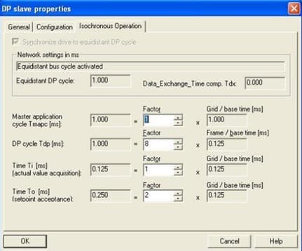
Q: When using the D410 the error “Synchronization error between Profibus and Profinet” popped up. What can we do?
A: Both systems have to use the same cycle time. If the Profinet cycle time is 1ms then Profibus must use the same one. See the next screenshot for 1ms settings.
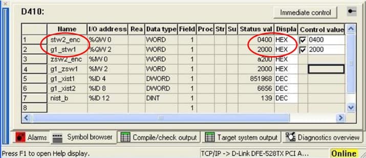
Q: Why don’t I get back position values in G1_XIST2 (Telegram 81-84)?
A: According to the encoder profile it is necessary to set Bit 10 to “1” in STW2 and Bit 13 in G1_STW1. See the next hardcopy. Or an error is given and is not confirmed.
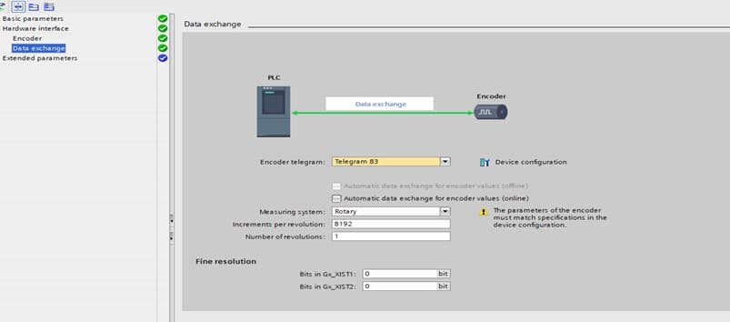
Q: How to configure Technology Objects in Tia Portal?
A: When using the Siemens Technology object, please do the following configuration:
1. Increments per revolution and Number of revolutions: according to your encoder. 2. Fine resolution set to 0 (see the screenshot)
Remark! Please see the image attached. The configuration is done for a Single Turn Encoder. You must set Increments per revolution and Number of revolutions according to the encoder you are using.

Q: Round Axis
A: In TWK encoder is no round axis integrated. If the customer sets e.g. number of turns to 24, then the encoder autonomously sets internal next higher 2^n number of turns available in the measuring range. The mismatch to the configured setup in the config tool and encoder will be detected by checksum issues. Explanation of behavior see in the manual on page 44 or chapter 6.1.2 Description of the Absolute Encoder Parameter.
Q: On which resolution velocity calculation is based on?
A: The velocity is always based on the raw value and not on the scaled one and additional always based on 12 bit Single-Turn resolution, even when a 13-bit resolution type as single-turn is used!! For low speed you need to consider linearity of 0.2% per revolution and quantization issue of the resolution. Monitoring of both channels is based on position value and velocity calculated on one of both. Integration time takes a real position value difference at logging time. Each 1 ms a new velocity value is calculated. Example: integration time 1 s. That means the encoder stores 1000 position values and is calculating a position difference between 1 sec.
Q: Why there are Just 0 Values as Process Value?
A: The same behavior as above can be also observed when the wrong device class is selected like TIA instead of NON-TIA from the device type. Please check type label information and selected device type in the project tool.
Q: How to use Profisafe Encoder with Draw Wire?
A: It is strongly not recommended to use a standard Profisafe encoder together with a drawer wire sensor. Root cause for this restriction: The torque needed to drive the encoder shaft is quite high and the spring inside the draw sensor may be blocked. This failure case is not allowed for a safety device.
Q: What is the capability of ABB SM560 safety PLC?
A: This type of PLC just supports 16-bit data safety consistency and NON-TIA version shall be used.
Q: Is it possible to use Profisafe encoder with other PLC manufacturers than SIEMENS?
A: This is in principle possible as Profisafe is a generic interface and not binded to one PLC manufacturer brand. BUT you need to check if 32-bit safety values can be handled as one consistent value or not. In case 32 Bit consistent value can be handled, then use TIA version otherwise NON-TIA version.
Q: What does the error message: Internal communication error TPS-1 means?
A: This message occurs very seldom as I heard from TWK. Maybe it is related to a soldering problem on the PCB which interrupts the communication between their ProfiNet controller and their main controller or it is related to EMC issues in the installation. Regarding EMC all our standard measures should be considered as usual as shielded cables, good electrical connection between encoder flange and machine/potential earth, no ground loops, ...
Q: Why do I see just 0 Values in the Watch Window?
A: If the general integration of the encoder in the project was successful like naming, address and so on and the LEDs indicate a green status, but you get only 0 values in the watch window, then you have not used Process Data Input values from the safety encoder in the safety program. Only when the encoder is used in F-program (safety related), then the Profisafe communication is started with the encoder.
This explains why you see 0 values, when the process values like position or velocity are not used in the safety program. Furthermore, in the TIA portal version you can use a so called acknowledge global flag for automatic re-insertion of all failed devices.
Q: How to use Device Address
A: The number of the device address must match in the device name with the setting under F- parameter with F_Dest_Add. See here also hints in the manual chapter 4.2.5.1.
Q: How to set Preset value?
A: Within the control word the bit must be set to activate the preset value. In the "data stream" the control word, preset value and F-data must be sent. Be aware that the control bit must be set back to 0, because only with the rising slope of the bit control flag the preset value is overtaken.
Q: Which material should be used for salt water?
A: V4A stainless steel version is recommended for salt water.