IXARC Incremental Encoder
UCD-IPH00-XXXXX-R060-2AW
POSITAL
Measuring Tools & Sensors
Programmable HTL/TTL - Default Push-Pull (HTL), Cable - Axial 2 m, A, B, Z, /A, /B, /Z, IP64 / IP65, Aluminum / Steel, Solid Shaft - Synchro, ø 36 mm (1.42"), ø 6 mm (0.24")
Available
0

| Interface | |
| Interface | Programmable Incremental |
| Programming Functions | PPR (1-16384), Output, Counting Direction |
| Configuration Tool | UBIFAST Configuration Tool (Version ≥ 1.6.3) |
| Outputs | |
| Output Driver | Push-Pull (HTL) |
| Output Voltage High Level Push-Pull (HTL) | > 4 V @ 4.75-9 V Supply Voltage
> V-3 V @ 9-30 V Supply Voltage |
| Output Voltage Low Level Push-Pull (HTL) | < 0.5 V |
| Output Voltage High Level RS422 (TTL) | > 4 V |
| Output Voltage Low Level RS422 (TTL) | < 0.5 V |
| Maximum Frequency Response | 1 MHz |
| Maximum Switching Current | 50 mA per Channel |
| Electrical Data | |
| Supply Voltage | 4.75 – 30 VDC |
| Current Consumption | ≤140mA @ 5V DC, ≤70mA @ 10V DC, ≤40mA @ 24V DC |
| Power Consumption | ≤ 1.0 W |
| Start-Up Time | < 1 s |
| Min. Load Resistance | 120 Ω |
| Reverse Polarity Protection | Yes |
| Short Circuit Protection | Yes |
| EMC: Emitted Interference | DIN EN 61000-6-4 |
| EMC: Noise Immunity | DIN EN 61000-6-2 |
| MTTF | 280 years @ 40 °C |
| Sensor | |
| Technology | Magnetic |
| Accuracy (INL) | ±0.0878° (≤ 12 bit) |
| Duty Cycle | 180° ± 27° (Speed > 100RPM) |
| Phase Angle | 90° ± 14° (Speed > 100RPM) |
| Environmental Specifications | |
| Protection Class (Shaft) | IP65 |
| Protection Class (Housing) | IP65 |
| Operating Temperature | -30 °C fixed (-22 °F), -5 °C flexible (+23 °F) - +80 °C (+176 °F) |
| Humidity | 98% RH, no condensation |
| Mechanical Data | |
| Housing Material | Steel |
| Housing Coating | Cathodic corrosion protection (>720 hrs salt spray resistance) |
| Flange Type | Synchro, ø 36 mm |
| Flange Material | Aluminum |
| Shaft Type | Solid, Length = 11.5 mm |
| Shaft Diameter | ø 6 mm (0.24") |
| Shaft Material | Stainless Steel V2A (1.4305, 303) |
| Max. Shaft Load | Axial 40 N, Radial 110 N |
| Friction Torque | ≤ 3 Ncm @ 20 °C (4.2 oz-in @ 68 °F) |
| Max. Permissible Mechanical Speed | ≤ 12000 1/min |
| Shock Resistance | ≤ 100 g (half sine 6 ms, EN 60068-2-27) |
| Permanent Shock Resistance | ≤ 10 g (half sine 16 ms, EN 60068-2-29) |
| Vibration Resistance | ≤ 10 g (10 Hz – 1000 Hz, EN 60068-2-6) |
| Length | 43 mm (1.69") |
| Weight | 505 g (1.11 lb) |
Minimum Mechanical Lifetime
(10^8 revolutions with Fa/Fr) | 40 (20 N / 40 N), 14 (40 N / 60 N), 10 (40 N / 80 N), 6 (40 N / 110 N) |
| Electrical Connection | |
| Connection Orientation | Axial |
| Connector | Cable 2 m |
| Cable Length | 2 m [79"] |
| Wire Cross Section | 0.14 mm² / AWG 26 |
| Material / Type | PVC |
| Cable Diameter | 6 mm (0.24 in) |
| Minimum Bend Radius | 46 mm (1.81") fixed, 61 mm (2.4") flexing |
| Product Life Cycle | |
| Product Life Cycle | Exiting |
| Connection Plan | |
| SIGNAL | CABLE COLOR |
| A | Green |
| /A | Yellow |
| B | Gray |
| /B | Pink |
| Z | Blue |
| /Z | Red |
| Power Supply | Brown |
| GND | White |
| Shielding | Shield |
Connector-View on Encoder
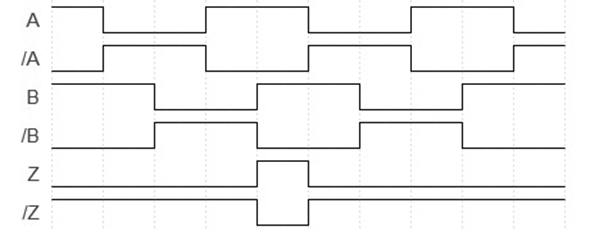
Pulse Diagram

Rotation Clockwise (seen on shaft)
If the drawings are not available please refer to the "Download" section.
The picture and drawing are for general presentation purposes only. All dimension in [inch] mm.
© FRABA B.V., All rights reserved. We do not assume responsibility for technical inaccuracies or omissions. Specifications are subject to change without notice.


